Since my lightsaber project is quite extensive, I will divide it in a multiple of blog posts. This one is about hardware.
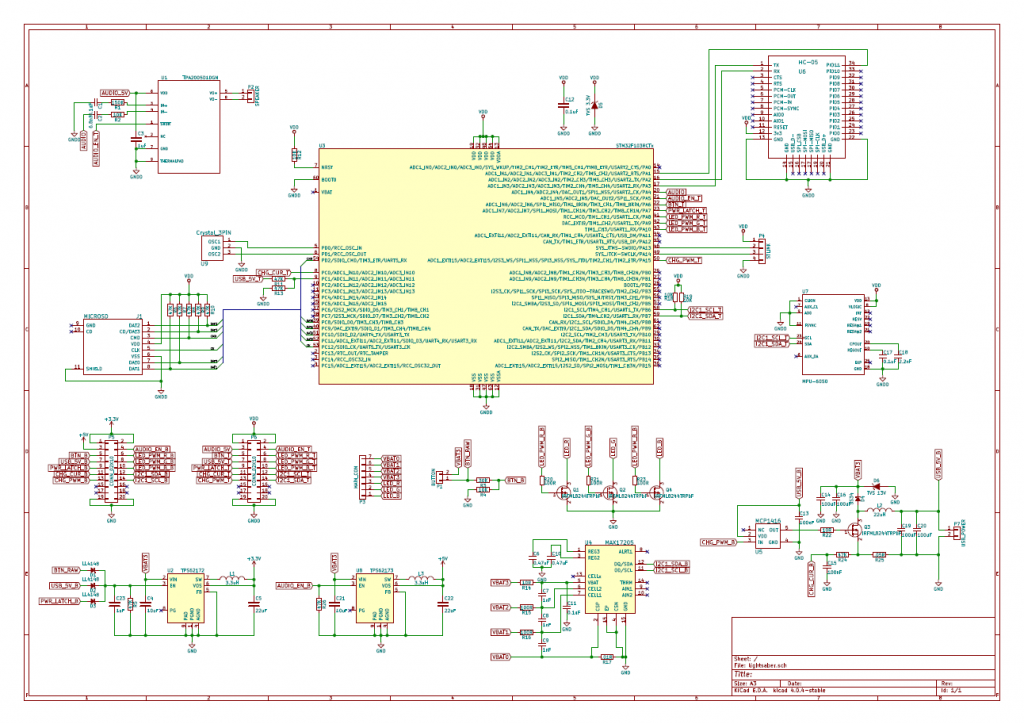
Click on the schematic image to open PDF.
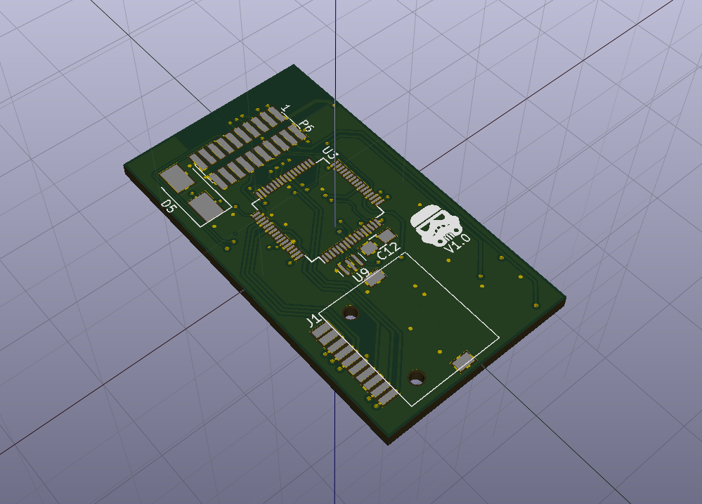
Hardware is divided into 2 PCBs to fit into the handle. Power electronics are on bottom board and digital stuff is on the top board. They are interconnected via P5-P6 connectors.
Main microcontroller is STM32F103RCT6. Main requirements were: SDIO and DAC with DMA capability for audio, and plenty of generic peripherals for other hardware. For a 2 EUR price point this microcontroller was the single choice.
Digital circuitry is power by 3.3 V so to step down from 3S lithium (12.6 V) I chose a switching converter. Linear regulator would heat too much with such a wide voltage difference and currents up to 200 mA. I chose TPS62172 because of their simplicity and my struct space requirements. Only 2 capacitors and an inductor is required for operation. These converters have factory set voltages so no feedback circuit ir required. TPS62173 from the same line was chose to power 5V audio amplifier.
To prevent excessive stand-by power drain, converters are turned off. They can be enabled by 3 different sources: button click, USB charger connection or main controller latch. Once button is clicked, microcontroller is powered and quickly latches the power and holds it until shut down condition.
Since I’m using 3S lithium configuration, battery protection is a must. MAX17205 was chosen as battery management IC. It has a full lithium fuel gauge algorithm and integrated balancing transistors so it was a perfect fit here. There were other cheaper chips from TI but they did not have any documentation. Probably laptop battery manufacturers are very scared of 3rd party batteries.
Batteries are charged from 5V USB power, but there is one big problem with USB charging. There are no widely adopted standards for determining maximum current. Many manufacturers use brute force method which gradually ramps up current until voltage starts to drop and then backs off a bit. But there are no converter chips for this method so I had to design my own boost converter which consists of MOSFET Q3, inductor L2 and diode D4. It was designed to work in 100-500 kHz frequency range with currents up to 3 A. Input current is measured over shunt R25 and low pass filter formed by R24, C15.
TPA2005 is a filterless class D audio amplifier. It was chosen to avoid having additional heatsinks.
Bluetooth interface is implemented with a cheapest HC-05 module which is more than enough for this application. It communicates with MCU through UART interface with additional control signal which selects command/data modes.
MPU-6050 is an accelerometer/gyroscope combo for swing detection.
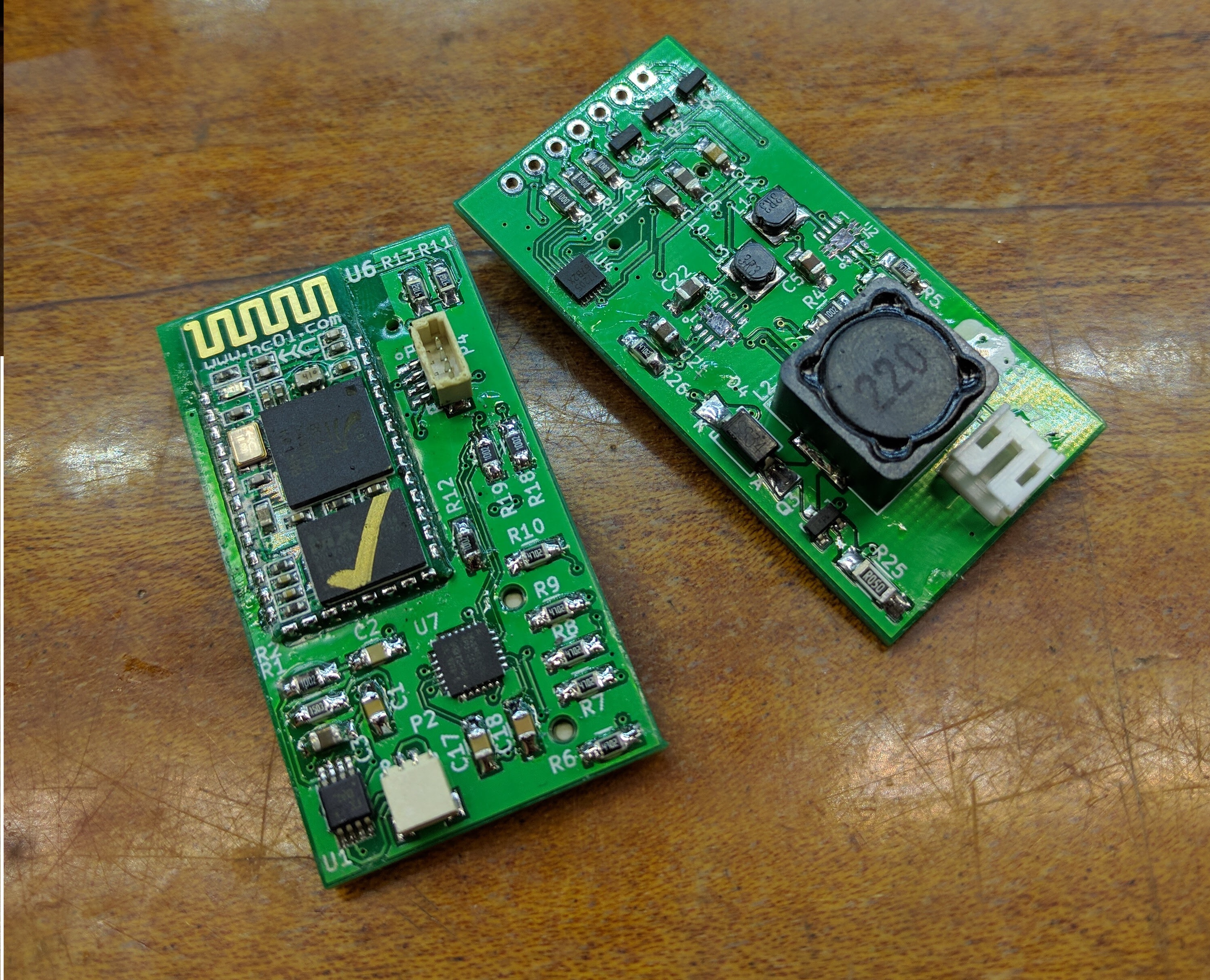
Soldering of the PCBs took almost 3 hours.