This is a part 2 of my soldering station build. Main difference – T12 soldering tips instead of old 900M tips. T12 tips are superior because they have heating element and temperature sensor embedded directly into the tip itself, giving maximum thermal conductivity and most accurate temperature control. T12 tips also heat up much quicker.
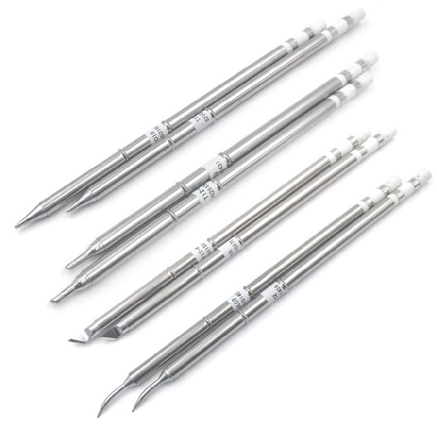
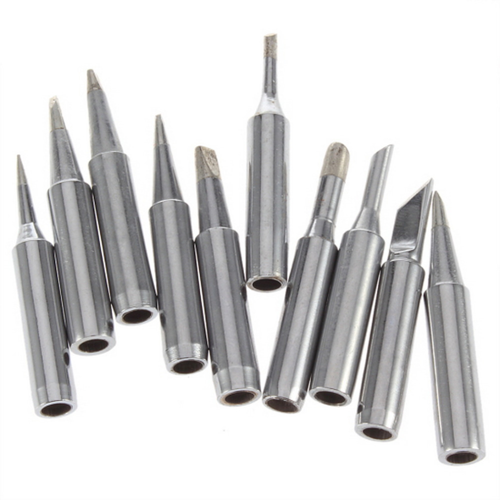
Here you can see the difference between these two types of tips: T12 (top) and 900M (bottom). T12 has connections on the end for heating element and sensor while 900M has a hole where external heating element with sensor is inserted and that gives very poor temperature control due to sensor measuring heater temp instead of the tip.
One challenge with using T12 tips is that they are using thermocouple in series with heater element so you can only measure temperature when heater is off. This requires a bit of additional electronics and high side heater switching. Bellow you can see schematic of the soldering station.
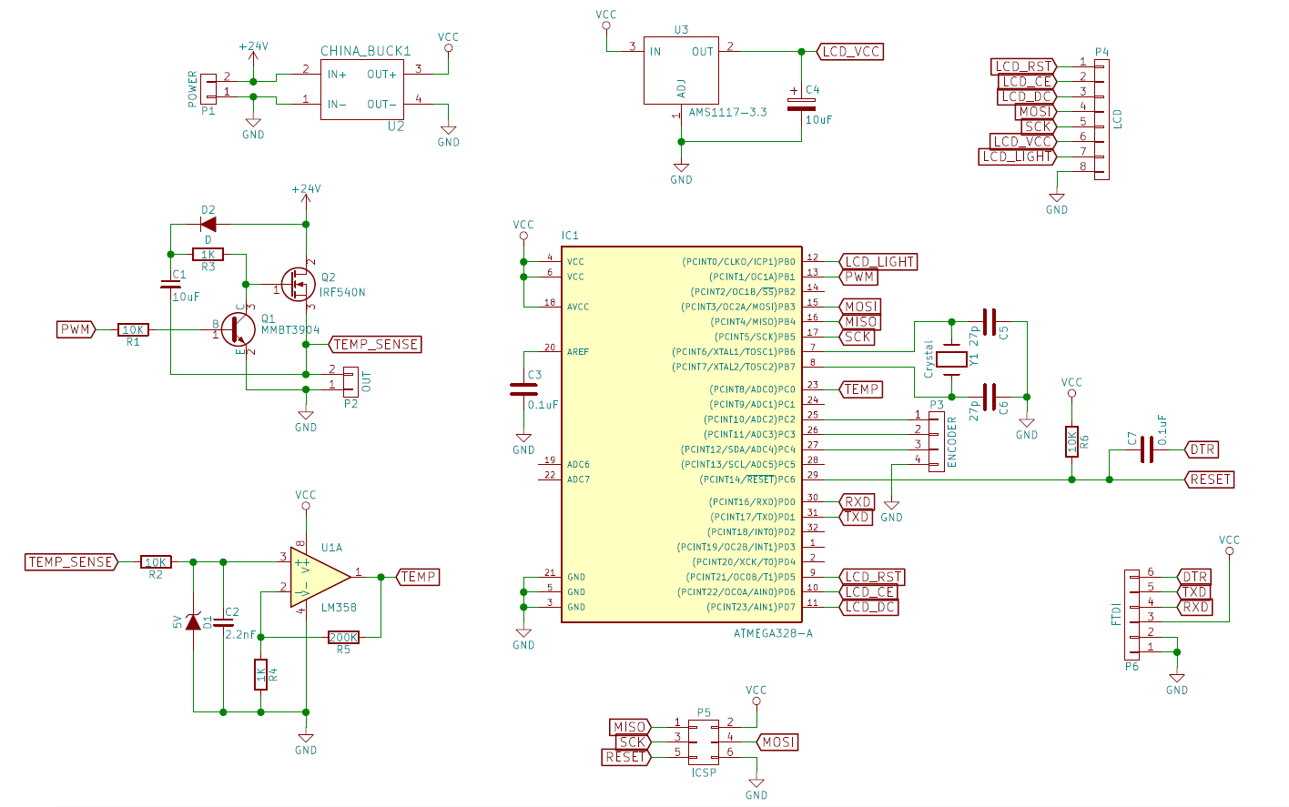
Heater element is switched with Q2 N-channel MOSFET. Since it is in high side configuration, charge pump was added to raise gate above 24V. I could have used just a P-channel MOSFET here, but they are less efficient (probably not a problem here) and I wanted to experiment with charge pumps.
Thermocouple signal is filtered by R2, C2 low pass filter and amplified by LMV358 op-amp (schematic says LM358, but you need LMV358 here due to its rail-to-rail output). D1 5V zener is there to prevent high voltage entering op-amp when the heater is on.
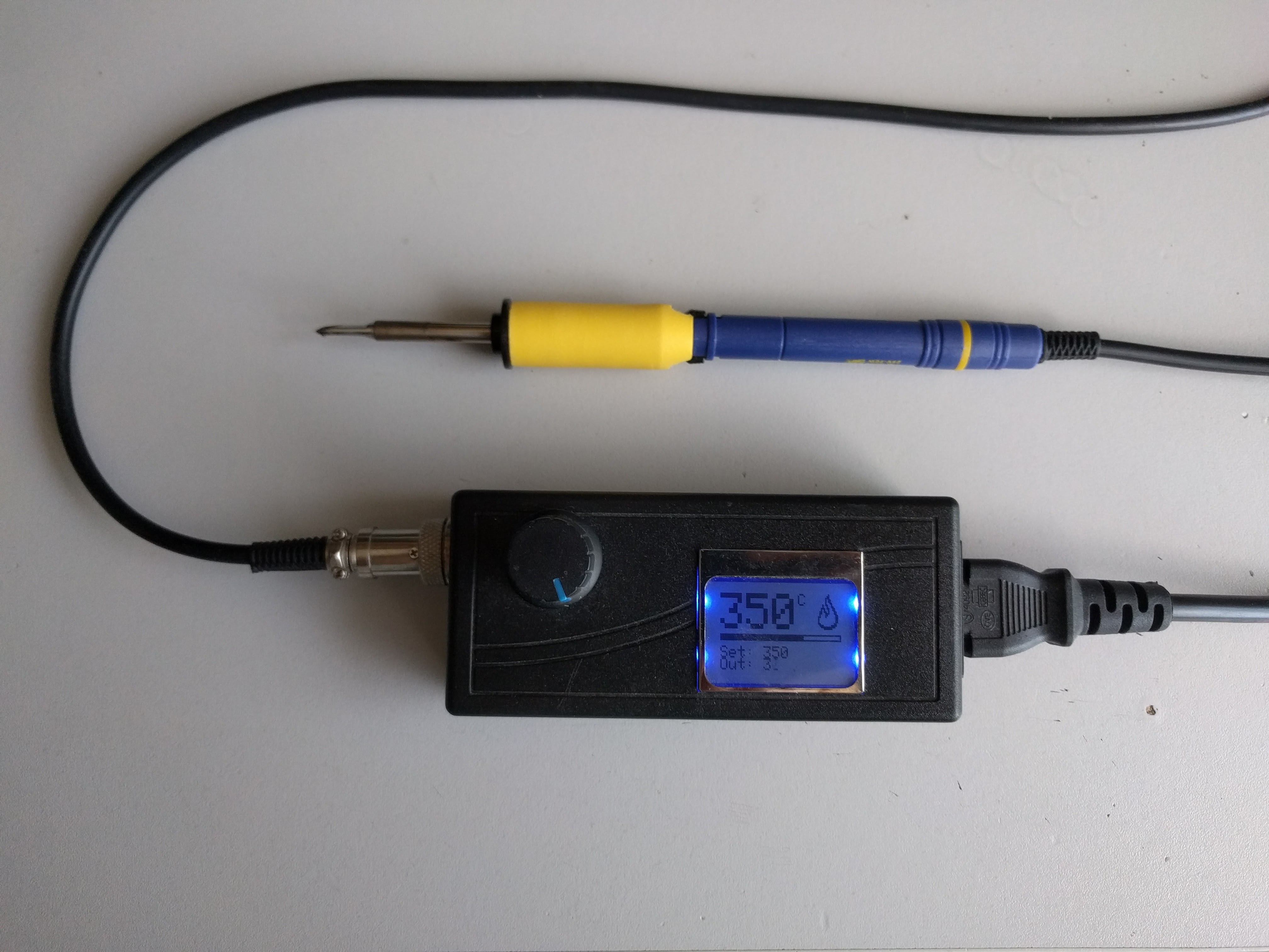
Everything is controlled by Atmega328 MCU. Display is generic Nokia 3310. Temperature is selected with a rotary encoder.
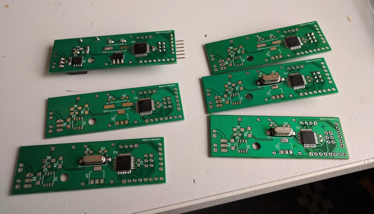
PCBs were manufactured by iTead (10 pcs for 19$). Now you may ask why there are 6 PCBs soldered in the photo above? I spent whole day trying to figure out why none of the boards can be programmed via ISP. Until I tried to desolder working Atmega328 from arduino and place it on my board. Turns out that all 20 atmegas that I got from china were dead. Maybe packaging them in plastic Pro-ESD wrap was not a good idea CHINA. But apparently they still ship most of their chips that way.
Anyway, once everything was working it was time to write simple firmware and calibrate PID controller. I also calibrated temperature sensor by using external thermocouple attached to the tip:
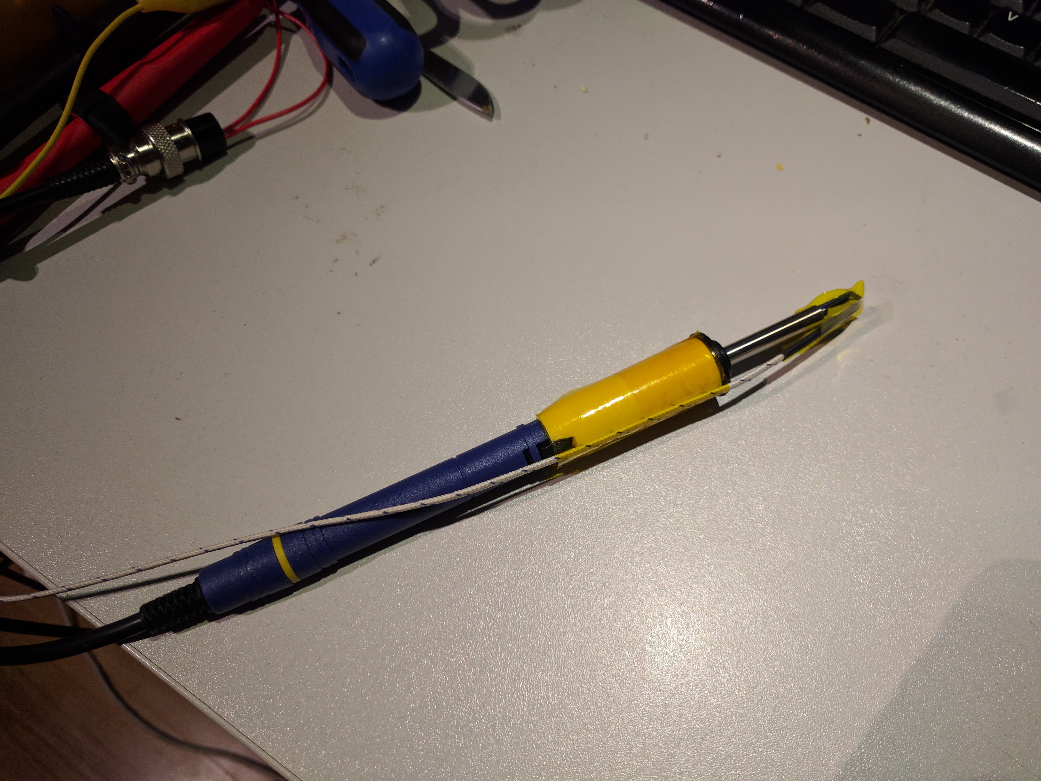
I just manually plotted ADC voltage readings vs external thermocouple readings in Excel and fitted a quadratic curve over the data.
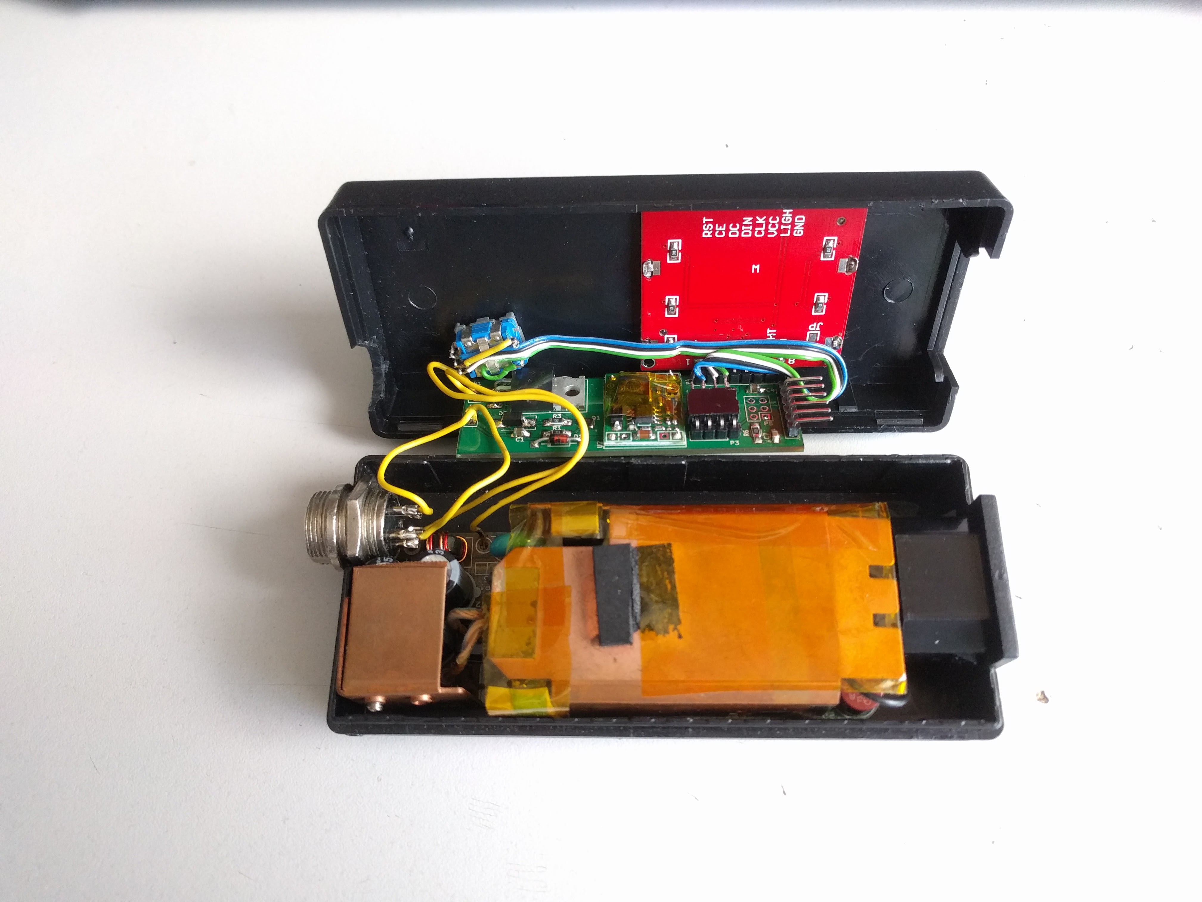
Everything fitted nicely in a 24V power supply brick. It is surprising how they left so much free space inside.
Arduino code:
#include <JC_Button.h>
#include <Event.h>
#include <Timer.h>
#include <PID_v1.h>
#include <SPI.h>
#include <Adafruit_GFX.h>
#include <Adafruit_PCD8544.h>


// Hardware SPI (faster, but must use certain hardware pins):
// SCK is LCD serial clock (SCLK) - this is pin 13 on Arduino Uno
// MOSI is LCD DIN - this is pin 11 on an Arduino Uno
// pin 5 - Data/Command select (D/C)
// pin 4 - LCD chip select (CS)
// pin 3 - LCD reset (RST)
Adafruit_PCD8544 display = Adafruit_PCD8544(7, 6, 5);

bool enabled = true;

//Define Variables we'll be connecting to
double Setpoint, Input, Output;
double CurrentTemp;

//Define the aggressive and conservative Tuning Parameters
double aggKp=20, aggKi=0, aggKd=1;
double consKp=20, consKi=1, consKd=1;

//Specify the links and initial tuning parameters
PID ctrl(&Input, &Output, &Setpoint, aggKp, aggKi, aggKd, DIRECT);

#define TEMP_MIN 100
#define TEMP_MAX 500

// Pins
#define SENSOR_PIN A0
#define CONTROL_PIN 9
#define ROTARY_1_PIN A3
#define ROTARY_2_PIN A4
#define BUTTON_PIN A2
#define LCD_LIGHT_PIN 8

// Rotary encoder
bool lastRot = false;
int8_t accel;

#define PULLUP true
#define INVERT true
#define DEBOUNCE_MS 20
#define LONG_PRESS 1500
Button btn(BUTTON_PIN, DEBOUNCE_MS, PULLUP, INVERT);

// Timer
Timer t;

#define ROTARY_CHECK_INTERVAL 3
int8_t rotaryCheckTimer = NO_TIMER_AVAILABLE;

#define LCD_REDRAW_INTERVAL 100
int8_t LCDRedrawTimer = NO_TIMER_AVAILABLE;

#define PID_UPDATE_INTERVAL 100
int8_t PIDUpdateTimer = NO_TIMER_AVAILABLE;

#define ADC_SAMPLE_INTERVAL 50
int8_t ADCSampleTimer = NO_TIMER_AVAILABLE;

// Fire icon bitmap
static const unsigned char PROGMEM fire_bmp[] =
{ B00000001, B00000000,
  B00000011, B00000000,
  B00000111, B00000000,
  B00000101, B10000000,
  B00000101, B10000000,
  B00000100, B11000000,
  B00010110, B01000000,
  B00010010, B01100000,
  B00111011, B00110000,
  B00101001, B00110000,
  B01101101, B00011000,
  B01100111, B00011000,
  B01000110, B00001100,
  B11000100, B00001100,
  B10000000, B00001100,
  B10000000, B00001100,
  B10000000, B00001100,
  B11000000, B00011000,
  B01110000, B01111000,
  B00111111, B11110000,
  B00001111, B11000000};


void setup() {
  Serial.begin(115200);

  //analogReference(INTERNAL);
  pinMode(SENSOR_PIN, INPUT);
  pinMode(CONTROL_PIN, OUTPUT);
  pinMode(LCD_LIGHT_PIN, INPUT);
  pinMode(ROTARY_1_PIN, INPUT_PULLUP);
  pinMode(ROTARY_2_PIN, INPUT_PULLUP);
  pinMode(BUTTON_PIN, INPUT_PULLUP);
  digitalWrite(LCD_LIGHT_PIN, LOW);

  //tell the PID to range between 0 and the full window size
  ctrl.SetOutputLimits(0, 255);
  ctrl.SetSampleTime(PID_UPDATE_INTERVAL);

  t.every(ROTARY_CHECK_INTERVAL, RotaryCheck);
  t.every(PID_UPDATE_INTERVAL, PIDUpdate);
  t.every(LCD_REDRAW_INTERVAL, LCDRedraw);
  t.every(ADC_SAMPLE_INTERVAL, ADCSample);

  display.begin();
  // init done

  // you can change the contrast around to adapt the display
  // for the best viewing!
  display.setContrast(60);

  // Initial temp
  Setpoint = 350;

  Enable();
}

// Rotary encoder with acceleration
void RotaryCheck()
{
  bool newRot = digitalRead(ROTARY_1_PIN);

  if (!newRot && lastRot)
  {
    if (!digitalRead(ROTARY_2_PIN))
    {
      Setpoint += accel;
      if (Setpoint > TEMP_MAX)
        Setpoint = TEMP_MAX;
    }
    else
    {
      Setpoint -= accel;
      if (Setpoint < TEMP_MIN)
        Setpoint = TEMP_MIN;
    }

    if (accel < 20)
      accel += 10;
  }
  else if (accel > 1)
    accel -= 1;

  lastRot = newRot;
}

void PIDUpdate()
{
  Input = CurrentTemp;

  double gap = abs(Setpoint-Input); //distance away from setpoint
  if (gap < 20)
    ctrl.SetTunings(consKp, consKi, consKd);
  else
    ctrl.SetTunings(aggKp, aggKi, aggKd);

  ctrl.Compute();

  analogWrite(CONTROL_PIN, 255-Output);
}

void LCDRedraw()
{
  display.clearDisplay();

  display.setTextSize(3);
  display.setTextColor(BLACK);
  display.setCursor(0,0);
  display.print(CurrentTemp, 0);
  display.setTextSize(1);
  display.println("C");

  if (Output != 0)
  {
    display.drawBitmap(68, 0, fire_bmp, 16, 21, BLACK);
  }

  display.drawRect(0, 24, 84, 4, BLACK);
  display.fillRect(1, 25, 82*(CurrentTemp/TEMP_MAX), 1, BLACK);
  display.fillRect(1, 26, 82*(Setpoint/TEMP_MAX), 1, BLACK);
  display.setCursor(0,31);
  display.print("Set: ");
  display.println(Setpoint, 0);
  display.setCursor(0,38);
  display.print("Out: ");
  display.println(Output, 0);

  display.display();
}

unsigned long start;

// max 5
#define ADC_MULTISAMPLING 5
#define ADC_MULTISAMPLING_SAMPLES (1 << ADC_MULTISAMPLING)

// 7.1 ms
void ADCSample()
{
  analogWrite(CONTROL_PIN, 255);
  delayMicroseconds(300);

  // Filter ADC by multisampling
  int adc = 0;
  for (int i = 0; i < ADC_MULTISAMPLING_SAMPLES; ++i)
    adc += analogRead(SENSOR_PIN);
  adc = adc >> ADC_MULTISAMPLING;

  // Apply quadratic equation to get temperature
  double temp = -0.0013*adc*adc + 1.696*adc - 59.284;

  // Additional temperature filtering
  CurrentTemp += (temp-CurrentTemp)*0.05;

  analogWrite(CONTROL_PIN, 255-Output);
}

void Enable()
{
  pinMode(LCD_LIGHT_PIN, OUTPUT);

  ctrl.SetMode(AUTOMATIC);

  enabled = true;
}

void Disable()
{
  pinMode(LCD_LIGHT_PIN, INPUT);

  ctrl.SetMode(MANUAL);
  Output = 0;

  enabled = false;
}

void loop() {
  t.update();
  btn.read();

  if (btn.wasPressed())
  {
    if (enabled)
      Disable();
    else
      Enable();
  }
}
Libraries used:
- https://github.com/JChristensen/Timer
- https://github.com/JChristensen/JC_Button
- https://github.com/br3ttb/Arduino-PID-Library
- Adafruit GFX and PCD8544 libraries from arduino repository
EDIT 5/21/2018:
JChristensen/Button library was renamed to JC_Button. Source code and links updated.
Looks nice, and a very nice clean and simple to read sketch.
I’m having trouble though trying to find which libraries you have used:
#include
#include
#include
– There’s a lot of different libraries that have “Timer.h” 😉
Updated post with a list of libraries 🙂
Hi, Just wondering what D1 is, is it just a normal 4148 diode or any specific?
D1 is a generic 5V zener diode. It limits the voltage on opamp input during on time. D2 is just a regular diode that can withstand power supply reverse voltage, current is minimal.
Thanks Jurgis
Can I replace the LMV358 with MCP602 ??
By the first look at the datasheet, it should work. Tell your results when you finish building 🙂
Hi, I have a problem with the button library. IDE 1.0.5, I also tested IDE 1.8. Ejects the message:
error: no matching function for call to ‘Button::Button(const uint8_t&, int, int, int)’
C:\Users\AN\Documents\Arduino\libraries\Button/Button.h:14: note: candidates are: Button::Button(uint8_t)
C:\Users\AN\Documents\Arduino\libraries\Button/Button.h:12: note: Button::Button(const Button&)
sketch_may20a.ino: In function ‘void loop()’:
sketch_may20a:251: error: ‘class Button’ has no member named ‘wasPressed’
What am I doing wrong ?
Looks like button library was renamed. Use this one: https://github.com/JChristensen/JC_Button and copy the new sketch code (post updated).
Unfortunately, I do something wrong or this method does not work. Can you ask for a step-by-step explanation?
I’ve added another Bell bible, and now the sketch.ino message appears: In function ‘void loop ()’:
sketch: 247: error: ‘class Button’ has no member named ‘read’
Code and libraries started to work on IDE 1.8.5, I have a question whether fusebits are factory-made or are they changed?
I think I used standard Arduino fuses. That is (atmega328):
uno.bootloader.low_fuses=0xff
uno.bootloader.high_fuses=0xde
uno.bootloader.extended_fuses=0x05
Why at the start, the display has a set temperature of 470, since the sketch is 350? What could be the reason for the error?
Strange. Does it work fine otherwise? The only part of code where Setpoint is changed is rotary encoder function. Do you have it connected on correct pins? Maybe there’s a bad connection and it generates false ticks. You could try disabling its timer at line 108 and see if problem fixes.
I replaced the encoder, nothing helped. I do not know how to turn off lines 108. Next after switching on is 470 C.
I reprogrammed atmege, there is improvement. Now he is not able to read the templature out. The SET function sets to 350, while the upper numbers of the nonstop change, so does the temperture out.
Thanks a lot for sharing! This is a really nice one, not too complex, but still pretty acurate. But there is something I don’t understand:
// Apply quadratic equation to get temperature
double temp = -0.0013*adc*adc + 1.696*adc – 59.284;
// Additional temperature filtering
CurrentTemp += (temp-CurrentTemp)*0.05;
What are these numbers? Where do you have them from? Could you please explain the formula?
Thank you i advance.
Greetings, Willi
Hey, thanks for your interest in this project.
The quadratic equation translates raw ADC readings to actual temperature in celsius. You could use K type thermocouple equation to calculate it, but it would not compensate for offsets in electronics and the thermal characteristics of the tip itself. So I just plotted raw ADC readings vs actual temperature (measured by a precise thermocouple attached to the end of the tip) for the whole temperature range (about 10 C steps). Then I used excel (or any other plotting software) to calculate plot equation seen in the code. This equation now translates raw ADC readings to actual temperature at the end of the tip.
As for the second line about filtering, I found out that ADC readings have quite a bit of noise, probably due to nearby SMPS, long leads or bad PCB layout. It caused temperature jittering when near the set point, so I added that line as an additional filter. It basically adds error between measured temperature and filtered temperature multiplied by a filtering factor (0.05). Factor of 1 would mean no filtering at all as `CurrentTemp` would be equal to `temp`
Thanks, thats a very good answer 🙂 I will try it, I think that values needs to be individually calculated anyway, right? And I don’t like using things I don’t understand.
I have almost the same circuit as you, but for a 936 clone. Instead of a MOSFET I’m using a NPN 40V 10A transistor, the high side setup of the MOSFET is a good idea, and I have no Zener on the input, thats a great idea too, I have seen ways more complex projects but they all rely on the max input of the op-amps. I have also a Gain of ~201, exactly 196 for the iron and 198 for the hot air, but I use a Trimmer between Gnd and 220k Resistor on the amp output, so I can change the Gain and get already without PID relative good results, but it flickers a lot. I also press an external TC with the tip on hard wood. I have only a small window where I can get good results.
That remaining noise is the V-Offset of the LM358, every solder joint is like a thermocouple, someone asked already abot MPC60x op-amps, with that you can get better results, but I’m not sure if that much precisition is needed at all, what do you think?
If you are interested on developing it and like my idea withe that trimmer, maybe you can try it with your code, I can post my calculation if you like. I just orderen the T12, so it will take some weeks, before I can seriously try andthing, ony the PID on my existing station. I also have a more complex menu with some pages, setup for different things, like offset, hysteresis, standby time- and temperature etc. it is btw a 2in1 station wit the cheapest hot air gun we all know, but I like it 🙂
Thanks again!
I found a nice site for calculation, maybe someone finds it helpfull:
http://m.wolframalpha.com/examples/PlottingAndGraphics.html
Hi, I’m the beginner so I’m sorry for this type of question.
I want to make this project but instead of nokia display I want to use 1602 LCD. Can You recommend some site where I learn to modify code for using this screen? Or maybe You can tell me how to do that?
Many thanks.
Hey, no problem.
If you want to use 1602 LCD, you would have to replace Adafruit_PCD8544 library with https://www.arduino.cc/en/Reference/LiquidCrystal (or any other 16×2 LCD library). You would mainly have to change setup (display initialization) and LCDredraw functions to make it work. You can find a lot of LiquidCrystal library examples. Unfortunately some graphics are hard to replicate on 16×2 LCD, like temperature bar and fire icon. But you can just print set and current temperature values.
If you have trouble modifying the code, you can post it here (pastebin or so) and I will try to help and make it work 🙂
Thanks a lot! 🙂
At this moment I’m waiting for casing and handle but I’m trying to change some code. For example, I added 2×2 symbols fire icon and degree symbol. Works pretty well. Also, I changed backlight pin to add some sort of options menu in near future, where I can change contrast and backlight levels.
Also I have plans to add progmem library to store backlight and contrast options, as well as custom temperature settings and maybe some buzzer indicating set temperature.
Of course I will share this code if it will work 🙂
It’s working just fine!
I can’t wait for rest of parts.
Edited code and some bonus below 🙂
https://pastebin.com/DSehu8Nb
https://gfycat.com/SecondhandElectricFlatcoatretriever
That’s great! Waiting for parts is always frustrating. I’m always ordering extra to make a good electronics library 😀
OK, I added some message to plug soldering tip when sensor voltage is different than it should be with connected one. That was easy but now I want to make something different – I would like to set the temperature only when I press the encoder button, and the value in “set:” window changed by encoder and not confirmed by the button returns to the previous value after 3 seconds.
I know I should remove Enable() and Disable() and after that make new condition for that. If you have some example or source I will really appreciate that.
You can leave Enable/Disable functions as is, just remove them from loop, so they are not triggered by button press (or remap them to a button on different pin). Create a new global variable that holds a temporary set point, for example
double SetPointTempand then modify loop functions as such:void loop() {t.update();
btn.read();
if (btn.wasPressed())
SetPoint = SetPointTemp;
}
Also, change all SetPoint variables to SetPointTemp in RotaryCheck function.
To make it go back after 3 seconds you could start a timer in RotaryCheck function when rotation is detected and refresh it each time.
Hah, I completely forgot I ask You about that 😀
Thank You so much for your help, few days ago I had a breakthrough, I began to understand the code and syntax enough to edit and add functions by myself. I also added simple menu which will store settings in AVR’s flash memory. Backlight, contrast, buzzer and automatic suspend (yes, I added additional buzzer which is beeping when tip gets proper temperature, in options menu you can set tone, length and repeat times).
Suspend is added because I bought Hakko FX-9501 handle with ball switch – when its not activated station goes to suspend temp (another option in menu) in settable amount of time. Everything is closed inside of 936 clone casing, they are very cheap and looks quite nice.
Power supply is modified laptop psu, just changed output voltage from 16 to 24V at 75W. At final thing I want to put some plasti-dip coating on casing – Its just rubber in spray can, You can easily make casing real ESD protected.
That’s all 😀
Hi, Thank you for sharing this project, finally have good Diy soldering station.
And may i ask you why in my station the temp showing -52C at room temp ?
I suspect problems with the opamp circuit or maybe different thermocouple type in the tip? Anyway you could fix this by logging raw ADC readings in the serial and plotting temperature with external probe like I did. Then fit a curve over data with excel or some other plotting software and replace it in line 218.
Yes i’m using different opamp. Thank you for your explanation, will definitely try that
Hi, have you tried using fine tips like T12-Jl02 or T12-C08? I’ve also built a T12 controller but it uses thermostatic control instead of PID. I seem to have a problem with fine tips. If I touch a joint while micro soldering, it barely melts anything. It’s as if the temperature sensor takes some time to see the drop in temperature and start compensating. I don’t seem to have the same problem with a 936 clone which is using a similar control approach, similar tips and same temps. Thus I wonder if thermostatic control is useless for T12 or if the knockoff fine tips have barely or no copper at the tip.
Hey, I have the same problem with these fine tips, but I believe it’s due to poor thermal conduction in the tip. PID compensation is too slow due to thermal lag between tip and temperature sensor to react within reasonable time. I haven’t soldered with real T12 station so I don’t know if it’s the problem with the tips. Regarding your 936 clone, have you measured the exact temperature at the tip with an external probe? Maybe it’s higher than the set temperature and consequently melts solder quicker.
Hi! I have made one with similar design, but the mosfet heats a lot during the heating up of T12 tip. I’m using IRFZ44n Fet.
Hi,
Do you have a scope to check what’s happening on mosfet gate? Or just use a simple multimeter to measure voltage between source and gate (when it is heating at max duty cycle). It should be at least 5V for your mosfet to be fully on. Maybe bootstrap capacitor C1 is too low or missing?
Thanks for the reply. I’ve added a 10uf bootstrap capacitor and also checked the voltage between source and gate, maximum value is around 2.1V. Is it the charge pump that’s malfunctioning?
Voltage on the gate is way too low. It is not enough to fully turn on the transistor and causes it to heat. Some other debugging tips: check voltage on the charge pump capacitor, it should be close to power supply voltage. Other than that, it’s hard to say anything without a close look. Try double checking schematic and make sure that there are no bridges/open connections. Also, have you modified the software? The ADC read should not be disabled as it creates dead-time for the gate capacitor to charge.
Checked the voltage across capacitor, its 12V (Power supply-12V 3A). Schematics and connections seems to be right, I’ve used a printed circuit board.
Can I use a P-channel Mosfet instead?
Problem was with bootstrap capacitor. (Incorrect wiring)
Everything else works except for temperature control. I’m using Lm358 op amp. Is it necessary to replace it with Lmv358 rail to rail?
Yes, LM358 will show incorrect temperature, because temperature sense voltage is close to negative rail voltage (ground). This is why you need a rail to rail opamp.
Ok. Thanks
Hi Jurgis, very nice project.; I have assembled in a protoboard.; however the the iron doesn´t switch-on; I have some wiring doubts I would like to clarify with you :
SENSOR_PIN A0 – you mean the output of the LM358 (pin 1) connected to A0 port, in the schematic LABLED as “TEMP”; right ?
CONTROL_PIN 9 – you mean the PWM label in the schematic, from Q1 base to DIGITAL pin 9; is this correct ?
ROTARY ENCODER : I connected “CLK” to A3, “DT” to A4, “SW” to A2, “GND” to ground; but seems to be missing a connection to 5V.; if this is not connected the SET temperature (in the LCD) always counts upward.; if this correct ?
If there is some mistake above it may explain why the iron is not switching-on; very much appreciate your help on this.; thank you
Sir, can the LCD be replaced with LCD 1602? thank you
Can you ask for gerber files?